CCIE

:OSPF Series: Impact of non-broadcast on MD5 key rollover

I ran across an issue when trying to use different MD5 cryptographic keys on the same interface for multiple neighbors. I originally thought that it was an bug with GNS3/IOU or the IOS version, but after running through multiple versions and even firing up VIRL it acted the same so I had to dig a bit deeper. I’m really glad that I did, because I uncovered a gap in my knowledge.

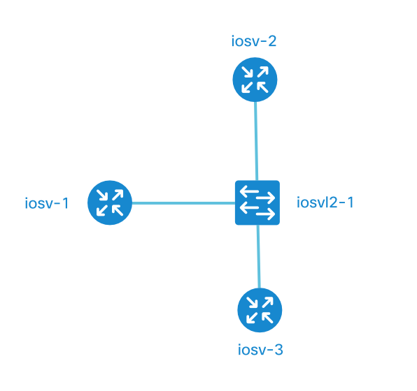
The topology is simple, 3 routers connected on a single VLAN.  iosv-1 is acting as the “hub” with iosv-2 and iosv-3 as the spokes, not forming direct OSPF neighbor relationships.

The idea was to have OSPF MD5 authentication enabled, but with iosv-1 and iosv-3 using key-string 1STKEY and iosv-1 and iosv-2 using key-string 2NDKEY.


ccie, cciev5, ospf

router iosv-1

interface GigabitEthernet0/1
description to iosvl2-1
ip address 10.0.0.1 255.255.0.0
ip ospf authentication message-digest
ip ospf message-digest-key 1 md5 1STKEY
ip ospf message-digest-key 2 md5 2NDKEY

router ospf 1
network 10.0.0.0 0.0.255.255 area 0
neighbor 10.0.0.3
neighbor 10.0.0.2

router iosv-2

interface GigabitEthernet0/1
description to iosvl2-1
ip address 10.0.0.2 255.255.0.0
ip ospf authentication message-digest
ip ospf message-digest-key 2 md5 2NDKEY

router ospf 1
network 10.0.0.0 0.0.255.255 area 0

router iosv-3

interface GigabitEthernet0/1
description to iosvl2-1
ip address 10.0.0.3 255.255.0.0
ip ospf authentication message-digest
ip ospf message-digest-key 1 md5 1STKEY

router ospf 1
network 10.0.0.0 0.0.255.255 area 0

But it would never form stable OSPF neighbor relationships with both routers. Looking at the output, it would form with iosv-2 but not iosv-3.

 iosv-1#sh ip ospf neighbor
192.168.0.2 0 FULL/ - 00:01:42 10.0.0.2 GigabitEthernet0/1

iosv-1#show ip ospf interface g0/1
....
Cryptographic authentication enabled
Youngest key id is 2

iosv-1#debug ip ospf adj
iosv-1#debug ip ospf packet

iosv-1#
*May 24 15:03:19.371: OSPF-1 ADJ Gi0/1: Send with youngest Key 2
*May 24 15:03:48.409: OSPF-1 ADJ Gi0/1: Send with youngest Key 2

*May 24 15:06:40.336: OSPF-1 PAK : Gi0/1: OUT: 10.0.0.1;10.0.0.3: ver:2 type:1 len:48 rid:192.168.0.1 area:0.0.0.0 chksum:0 auth:2 keyid:2 seq:0x5561
*May 24 15:06:40.337: OSPF-1 PAK : Gi0/1: OUT: 10.0.0.1;10.0.0.2: ver:2 type:1 len:48 rid:192.168.0.1 area:0.0.0.0 chksum:0 auth:2 keyid:2 seq:0x5561


iosv-3#
*May 24 15:07:50.676: OSPF-1 ADJ Gi0/1: Send with youngest Key 1
*May 24 15:08:11.110: OSPF-1 PAK : Gi0/1: IN: 10.0.0.1;10.0.0.3: ver:2 type:1 len:48 rid:192.168.0.1 area:0.0.0.0 chksum:0 auth:2 keyid:2 seq:0x5561
*May 24 15:08:11.111: OSPF-1 ADJ Gi0/1: Rcv pkt from 10.0.0.1 : Mismatched Authentication Key - Invalid cryptographic authentication Key ID 2 on interface
*May 24 15:08:18.060: OSPF-1 ADJ Gi0/1: Send with youngest Key 1

iosv-3 is showing an error, saying that the MD5 key is mismatched. The authentication configuration looks correct and iosv-1 should accept md5 authentications using both keys. So let’s look into MD5 authentication a little deeper. This comes from ospf configuration guide

The system assumes its neighbors do not have the new key yet, so it begins a rollover process. It sends multiple copies of the same packet, each authenticated by different keys. The system sends out two copies of the same packet–the first one authenticated by key 1 and the second one authenticated by key 2…The system detects that a neighbor has the new key when it receives packets from the neighbor authenticated by the new key.

What it doesn’t specify is that when there are two keys on an interface, it will only use the youngest or last configured key when sending OSPF packets. The rollover process kicks in, only when the router receives an OSPF packet with the older key. When that happens the router will send duplicate OSPF packets with each of the MD5 keys.

So why isn’t iosv-3 sending OSPF packets with the MD5 key 1? If we look back at the configuration, iosv-1 has a neighbor statement configured but iosv-3 doesn’t.

By default a router will only send hellos with the last key configured, until it hears incoming hellos using older keys. If an incoming hello packet has a matching configured key, it will start sending hellos using this key as well.

The problem with our configuration is that when OSPF is configured as non-broadcast and only iosv-1 is sending OSPF hello packets as unicast to the configured neighbors iosv-2 and iosv-3. The routers iosv-2 and iosv-3 don’t have OSPF neighbor statements configured, so they never originate an OSPF hello with the configured older MD5 key.

If we configure neighbor statements for iosv-1 on iosv-2 iosv-3 the neighbors come up and if we look at iosv-1 you can see that it now sends duplicate OSPF packets using both MD5 keys (keyid:1 and keyid:2) out to both neighbors.

*May 24 15:22:50.224: OSPF-1 PAK : Gi0/1: OUT: 10.0.0.1;10.0.0.3: ver:2 type:1 len:52 rid:192.168.0.1 area:0.0.0.0 chksum:0 auth:2 keyid:1 seq:0x5561
*May 24 15:22:50.225: OSPF-1 PAK : Gi0/1: OUT: 10.0.0.1;10.0.0.2: ver:2 type:1 len:52 rid:192.168.0.1 area:0.0.0.0 chksum:0 auth:2 keyid:1 seq:0x5561
*May 24 15:22:50.226: OSPF-1 PAK : Gi0/1: OUT: 10.0.0.1;10.0.0.3: ver:2 type:1 len:52 rid:192.168.0.1 area:0.0.0.0 chksum:0 auth:2 keyid:2 seq:0x5561
*May 24 15:22:50.227: OSPF-1 PAK : Gi0/1: OUT: 10.0.0.1;10.0.0.2: ver:2 type:1 len:52 rid:192.168.0.1 area:0.0.0.0 chksum:0 auth:2 keyid:2 seq:0x5561

Looking at iosv-1 OSFP interface details for g0/1, you can see that it thinks that a key rollover is in progress which lets you use multiple keys for different neighbors.

iosv-1#sh ip ospf int g0/1
Cryptographic authentication enabled
Youngest key id is 2
Rollover in progress, 1 neighbor(s) using the old key(s):
key id 1 algorithm MD5

It’s amazing how a lack of basic understanding of a protocol can trip you up with trivial tasks.


Use Anki to randomize INE labs and CCIE study

I really like the INE Advanced Technology Labs but the one problem I had was studying them effectively.  Each of the labs is very specific to a certain technology or command, so knowing which command they are testing kind of gives it away.  What I wanted to do was create a way to remove the titles and allow me to jump straight into lab time with the least amount of friction.

My solution?  Use Anki to prompt me when to do the labs, and in the process I could remove the titles and make sure I knew which technology I should use to solve the task.  Anki uses spaced repetition, so in theory the things that are easy you should only have to repeat once a month or longer.  I use Anki for my normal CCIE flashcard studies and I think it works really well.  I still need to figure out how to tweak Anki for the labs to include a much longer initial timeframe for review.

ccie cciev5 flashcards anki

So far it’s working well!

:OSPF Series: Do virtual links impact traffic flows?

No not by default, but they can. There are a few factors that will influence the outcome.  If we take a design with multiple exit points from an OSPF area.

ospf ccie virtual-links transitcapability

Let’s look at the traffic flow from R9 to 99.99.99.9 which is a loopback of R10.  The traffic goes from R9 -> R2 -> R5 -> R8 -> R10.

R9#
R9#traceroute 99.99.99.9
Type escape sequence to abort.
Tracing the route to 99.99.99.9
VRF info: (vrf in name/id, vrf out name/id)
1 100.100.29.2 2 msec 0 msec 1 msec
2 155.1.0.5 1 msec 2 msec 1 msec
3 155.1.58.8 1 msec 2 msec 1 msec
4 155.1.108.10 7 msec * 3 msec

R9#sh ip route 99.99.99.9
Routing entry for 99.99.99.0/24
Known via "ospf 1", distance 110, metric 1031, type inter area
Last update from 100.100.29.2 on Ethernet0/0.29, 01:01:05 ago
Routing Descriptor Blocks:
* 100.100.29.2, from 150.1.2.2, 01:01:05 ago, via Ethernet0/0.29
Route metric is 1031, traffic share count is 1

Let’s take a look into the OSPF database for the summary 99.99.99.0/24.  We can see that the advertising routers are R2 and R3.

R9#sh ip ospf database sum 99.99.99.0
OSPF Router with ID (150.1.9.9) (Process ID 1)

Summary Net Link States (Area 2)

Routing Bit Set on this LSA in topology Base with MTID 0
LS age: 1679
Options: (No TOS-capability, DC, Upward)
LS Type: Summary Links(Network)
Link State ID: 99.99.99.0 (summary Network Number)
Advertising Router: 150.1.2.2
LS Seq Number: 80000002
Checksum: 0x274E
Length: 28
Network Mask: /24
MTID: 0 Metric: 1021

LS age: 482
Options: (No TOS-capability, DC, Upward)
LS Type: Summary Links(Network)
Link State ID: 99.99.99.0 (summary Network Number)
Advertising Router: 150.1.3.3
LS Seq Number: 80000001
Checksum: 0x1C58
Length: 28
Network Mask: /24
MTID: 0 Metric: 1021

Now we setup a virtual link between R9 and R3 setup. Note the change in ospf database, routing bit changed to Area 0 route, but the actual data path didn’t change.

R9#sh ip ospf data summ 99.99.99.0

OSPF Router with ID (150.1.9.9) (Process ID 1)

Summary Net Link States (Area 0)

Routing Bit Set on this LSA in topology Base with MTID 0
LS age: 1684 (DoNotAge)
Options: (No TOS-capability, DC, Upward)
LS Type: Summary Links(Network)
Link State ID: 99.99.99.0 (summary Network Number)
Advertising Router: 150.1.5.5
LS Seq Number: 80000002
Checksum: 0xCB8F
Length: 28
Network Mask: /24
MTID: 0 Metric: 21

Summary Net Link States (Area 2)

LS age: 1789
Options: (No TOS-capability, DC, Upward)
LS Type: Summary Links(Network)
Link State ID: 99.99.99.0 (summary Network Number)
Advertising Router: 150.1.2.2
LS Seq Number: 80000002
Checksum: 0x274E
Length: 28
Network Mask: /24
MTID: 0 Metric: 1021

LS age: 592
Options: (No TOS-capability, DC, Upward)
LS Type: Summary Links(Network)
Link State ID: 99.99.99.0 (summary Network Number)
Advertising Router: 150.1.3.3
LS Seq Number: 80000001
Checksum: 0x1C58
Length: 28
Network Mask: /24
MTID: 0 Metric: 1021

R9#traceroute 99.99.99.9
Type escape sequence to abort.
Tracing the route to 99.99.99.9
VRF info: (vrf in name/id, vrf out name/id)
1 100.100.29.2 1 msec 1 msec 0 msec
2 155.1.0.5 2 msec 1 msec 1 msec
3 155.1.58.8 1 msec 6 msec 2 msec
4 155.1.108.10 2 msec * 3 msec

R9#sh ip route 99.99.99.9
Routing entry for 99.99.99.0/24
Known via "ospf 1", distance 110, metric 1031, type inter area
Last update from 100.100.29.2 on Ethernet0/0.29, 00:02:32 ago
Routing Descriptor Blocks:
* 100.100.29.2, from 150.1.5.5, 00:02:32 ago, via Ethernet0/0.29
Route metric is 1031, traffic share count is 1

Now we turn off area transit capability. This removes the ability for the router to choose a non-area 0 optimal path.  As you can see below that the data path changed to follow the path through the virtual-link. R9 -> R7 -> R3 -> R5 -> R8 -> R10.

R9(config)#router ospf 1
R9(config-router)#no capability transit

R9#traceroute 99.99.99.9
1 100.100.79.7 3 msec 0 msec 1 msec
2 155.1.37.3 1 msec 0 msec 1 msec
3 155.1.0.5 2 msec 6 msec 1 msec
4 155.1.58.8 2 msec 2 msec 1 msec
5 155.1.108.10 2 msec * 4 msec

R9#sh ip ospf
Routing Process "ospf 1" with ID 150.1.9.9
Start time: 00:00:23.567, Time elapsed: 01:36:04.087
Supports only single TOS(TOS0) routes
Supports opaque LSA
Supports Link-local Signaling (LLS)
Does not support area transit capability

However this only changed R9’s view of the world, if R7’s route to 99.99.99.0/24 was through R2 this would create a routing loop. Due to the fact that R7’s best path is through R9 and R9 is trying to forward packets back to R7.

So let’s create that scenario, R2 tunnel interface bandwidth is 100M and R3 is 1M.

ospf ccie cciev5 virtual-link transit capability

R9# traceroute 99.99.99.9
  1 155.1.79.7 2 msec 1 msec 1 msec
  2 155.1.79.9 5 msec 1 msec 5 msec
  3  *  *  *

So can we traffic engineer the data flow R9 -> R7 -> R3 -> R5 -> R8 -> R10? Yes, if we turn off transit capability on R3, R7 and R9. We also need to daisy-chain virtual links together from R9->R7->R3.

ccie ospf ospf virtual-links

This is a pretty extreme corner case but it shows what transit capability tries to do, avoid routing loops and take the best path.

R9# traceroute 99.99.99.9
  1 155.1.79.7 1 msec 0 msec 1 msec
  2 155.1.37.3 1 msec 1 msec 1 msec
  3 155.1.0.5 2 msec 1 msec 1 msec
  4 155.1.58.8 6 msec 2 msec 2 msec
  5 155.1.108.10 2 msec *  4 msec

A quote from John T. Moy (one of the OSPF creators) “Virtual links allow summary-LSAs to be tunneled across nonbackbone areas, maintaining the desired hub-and-spoke topology for inter-area routing exchange.”

All the virtual-link allows is for the inter-area routing exchange to flow in a hub-and-spoke topology.  When area transit capability is enabled, the virtual link doesn’t impact the traffic flow. The funny thing is that no matter how many disjoined OSPF areas there are, if you string them together with virtual links they will act as a single area from a routing point of view.  They will take the shortest path through the network effectively bypassing all the intra/inter-area path selection steps.

TransitCapability
This parameter indicates whether the area can carry data traffic
that neither originates nor terminates in the area itself. This
parameter is calculated when the area's shortest-path tree is
built (see Section 16.1, where TransitCapability is set to TRUE
if and only if there are one or more fully adjacent virtual
links using the area as Transit area), and is used as an input
to a subsequent step of the routing table build process (see
Section 16.3). When an area's TransitCapability is set to TRUE,
the area is said to be a "transit area".

Link to RFC 2328

BGP CCIE ROUTING CERTIFICATION EIGRP

:CCIE Resources – OSPF:

This is a list of relevant sites/articles/books that I have found useful during my CCIE studies.

Core

OSPF RFC 2328

Book: OSPF: Anatomy of an Internet Routing Protocol

Advanced

RFC 4577 – OSPF as the Provider/Customer Edge Protocol for BGP/MPLS IP Virtual Private Networks (VPNs)

OSPF Support for Multi-VRF on CE Routers

Down-bit Ignore Feature in OSPFV2 PE-CE Scenario on Cisco NX-OS

OSPF PE: Downward bit, Super Area 0, Domain IDs, capability vrf-lite, sham links

When to Suppress OSPF Forwarding Address in Translated Type-5 LSAs

Book: MPLS Configuration on Cisco IOS Software

OSPF Route Filtering Demystified

Dijkstra’s Algorithm

:OSPF Series – Why won’t my OSPF route install?: What does Downward bit set/Non-backbone LSA mean?

This issue is related to an OSPF route that is in the OSPF database but doesn’t get installed in the routing table.

The sample topology is below.  R16 is a router, with the interfaces towards R17/R18 in a vrf called CustA.

OSPF, vrf-lit, VRF, MPLS, CCIE, CCIEv5

R16 isn’t installing R19’s loopback0 in the routing table.

show ip route vrf CustA
Routing Table: CustA
122.0.0.0/32 is subnetted, 2 subnets
O 122.1.1.17 [110/11] via 172.23.17.17, 00:00:45, Ethernet0/0.1617
O 122.1.1.18 [110/11] via 172.23.16.18, 00:00:45, Ethernet0/0.1618
 172.23.0.0/16 is variably subnetted, 5 subnets, 2 masks
O 172.23.18.0/24 [110/20] via 172.23.17.17, 00:00:45, Ethernet0/0.1617
 [110/20] via 172.23.16.18, 00:00:45, Ethernet0/0.1618
 192.168.1.0/32 is subnetted, 1 subnets
C 192.168.1.16 is directly connected, Loopback1

But 122.1.1.19 shows up in the OSPF database??

sh ip ospf database summary 122.1.1.19
OSPF Router with ID (192.168.1.16) (Process ID 2)
Summary Net Link States (Area 10)
LS age: 1564
 Options: (No TOS-capability, DC, Upward)
 LS Type: Summary Links(Network)
 Link State ID: 122.1.1.19 (summary Network Number)
 Advertising Router: 122.1.1.17
 LS Seq Number: 80000009
 Checksum: 0x16F6
 Length: 28
 Network Mask: /32
 MTID: 0 Metric: 11

So the next step was turning on debugging.  Specifically, debug ip ospf 2 spf which will show the output of any spf calculations.  After doing a shut/no shut on the R19 loopback the following debugs showed up:

OSPF-2 INTER: Start partial processing: type 3, LSID 122.1.1.19, mask 255.255.255.255,
OSPF-2 INTER: adv_rtr 122.1.1.17, age 3600, seq 0x80000002, area 10
OSPF-2 INTER: Downward bit set/Non-backbone LSA

So what does Downward bit set/Non-backbone LSA mean?

Well the Downward bit set, this originated in RFC4577 and is there to specifically address loop prevention when using OSPF as a PE-CE routing protocol for MPLS/BGP.  Specifically it addresses the issue of routes coming from the PE router’s BGP process being redistributed into OSPF, then from OSPF back to BGP which would cause a loop.  To get around this issue, the DN Bit was used to identify routes that are redistributed from a PE router to the CE router, once the DN Bit is set to 1 or Downward(in IOS) the route would be ignored by any other PE.  This also covers sites that are using multiple PE-CE routers and connections.

This makes sense that the PE Router ignores the LSA for SPF when the DN bit is set.  But it isn’t set in this case as you can see here in the pcap capture:

OSPF, vrf, wireshar

The DN bit is not set!  What now? So we have covered the Downward bit set part of the error message.  So it must be related to the second part of the message which is Non-backbone LSA.  If we go back to RFC4577 and look a little deeper there is a section on PEs and OSPF Area 0.  It states that “If a PE attaches to a CE via a link that is in a non-zero area, then the PE serves as an ABR for that area.”  So given that the PE functions as an area border router (ABR) for that area, they are allowed to flood inter-area routes to the CE using Type 3 LSAs.  The RFC also states that if the OSPF domain connecting to the PE router has any area 0 routers, they must connect to the PE directly or through a virtual link.

This means that the MPLS network functions as a “Super backbone”, allowing discontiguous area 0 networks to be disconnected but only if they are connected to the super backbone which functions as a third level of hierarchy above are 0.  This sounds like the issue, but we’re not running a super backbone running MPLS and BGP.  But if we look at the ospf process, by running show ip ospf it actually thinks we are connected to MPLS VPN Superbackbone shown below.

R16#sh ip ospf
 Routing Process "ospf 2" with ID 192.168.1.16
 Domain ID type 0x0005, value 0.0.0.2
 Start time: 00:00:49.870, Time elapsed: 10:47:03.240
 Supports only single TOS(TOS0) routes
 Supports opaque LSA
 Supports Link-local Signaling (LLS)
 Supports area transit capability
 Supports NSSA (compatible with RFC 3101)
 Connected to MPLS VPN Superbackbone, VRF CustA

Aaah, finally the router thinks because we are running ospf in a VRF we are automatically going to be treated as a PE and therefore we need to implement the loop prevention/design constraints.  Our route is being rejected because it’s coming from area 0, through to area 10 where R16 is acting as a PE router ignoring it.

So, we need to treat it like an MPLS enabled PE and turn off those loop prevention checks.  The command to do this is:

capability vrf-lite

From the Cisco site: The OSPF Support for Multi-VRF on CE Routers feature provides the capability of suppressing provider edge (PE) checks that are needed to prevent loops when the PE is performing a mutual redistribution of packets between the OSPF and BGP protocols. When VPN routing and forward (VRF) is used on a router that is not a PE (that is, one that is not running BGP), the checks can be turned off to allow for correct population of the VRF routing table with routes to IP prefixes.

As soon as this is enabled, the SPF runs and accepts the LSA.

OSPF-2 INTER: Start partial processing: type 3, LSID 122.1.1.19, mask 255.255.255.255,
OSPF-2 INTER: adv_rtr 122.1.1.17, age 1, seq 0x80000001, area 10
OSPF-2 SPF : Add better path to LSA ID 122.1.1.19, gateway 0.0.0.0, dist 21
OSPF-2 SPF : Add path: next-hop 172.23.17.17, interface Ethernet0/0.1617
OSPF-2 INTER: Add succeeded for summary route to 122.1.1.19/255.255.255.255, metric 21
OSPF-2 INTER: next-hop Ethernet0/0.1617/172.23.17.17, area 10

As you can see in this output the Routing Bit Set on this LSA which means that the route is valid and present in the routing table.

show ip ospf database summary 122.1.1.19
OSPF Router with ID (192.168.1.16) (Process ID 2)
Summary Net Link States (Area 10)
Routing Bit Set on this LSA in topology Base with MTID 0
 LS age: 79
 Options: (No TOS-capability, DC, Upward)
 LS Type: Summary Links(Network)
 Link State ID: 122.1.1.19 (summary Network Number)
 Advertising Router: 122.1.1.17
 LS Seq Number: 8000000A
 Checksum: 0x14F7
 Length: 28
 Network Mask: /32
 MTID: 0 Metric: 11

I have struggled with this for quite awhile, not knowing exactly why you should run capability vrf-lite.

Short answer, if you are running OSPF in a VRF you need to turn on the vrf-lite capability but it is extremely useful to understand exactly why.

BGP CCIE Redistribution

:BGP: Per-prefix path manipulation

I ran into an interesting issue a few weeks ago.  We were trying to get dynamic failover using BGP between two primary links.  This is usually a straightforward design, pre-pend AS-PATH on the secondary link and everything should work perfectly.  So when we tested it, the primary came up perfectly but when we failed over the secondary end-to-end reachability was lost.  When investigated R4/R5 was preferring a route through R6 which was a DR link.

BGP CCIE Redistribution

This was due to a static route on R6 that had been redistributed into the backbone BGP process.  The as-path length of 10.0.0.0/24 was 2 when coming from R6, but the AS-PATH length was 5 when coming from R2 due to the prepending.  Just a little refresher on the BGP path selection process.

Juniper BGP Best Path Selection link

1. Verify that the next hop can be resolved.
2. Choose the path with the lowest preference value (routing protocol process preference).
3. Prefer the path with higher local preference.
For non-BGP paths, choose the path with the lowest preference2 value.
4. If the accumulated interior gateway protocol (AIGP) attribute is enabled, prefer the path with the lower AIGP attribute.
5. Prefer the path with the shortest autonomous system (AS) path value (skipped if the as-path-ignore statement is configured).
6. Prefer the route with the lower origin code.

Cisco BGP Best Path Selection link

1. Prefer the path with the highest WEIGHT. - WEIGHT is a Cisco-specific parameter, which in this case we are multi-vendor so this isn't relevant.
2. Prefer the path with the highest LOCAL_PREF.
3. Prefer the path that was locally originated via a network or aggregate BGP subcommand or through redistribution from an IGP.
4. Prefer the path with the shortest AS_PATH.

***Each process is much more involved, but I’ve shortened them to what is relevant.

Ok, so thinking through the options.  When the primary link has failed, we want to prefer the secondary link over the DR link.  The DR link through R6 is being picked because the AS-PATH is lower.  WEIGHT can’t be used because R4 – R6 are Juniper devices, LOCAL_PREF can’t be used because R4/R5 and R6 are in a different AS.  LOCAL_PREF is only valid within an AS.  In the Cisco world you could prefer the correct path with the ORIGIN code, but in Juniper the AS_PATH is the next value that is evaluated.

– Block the redistribution of the static route from R6 into BGP.

Not possible in this instance due a restriction with not being able to modify the DR configuration.  Once the DR solution had been tested, it was locked down until the next re-test.

– Prepend from R6 towards the BBR.

Again restrictions on modifying the DR configuration made this impossible.

– Split 10.0.0.0 /24 into 2 x /25’s and advertise them over the primary/secondary links.

This relies on the longest prefix match of the router picking the longer /25 match vs. the /24.  This would definitely fix the immediate problem of not being able to use the secondary link, but the unintended consequence would be that R6 would also prefer the routes through R4/R5.  Not really a show stopper, but not the best design.

The last two possibilities were discussed but needed to be validated.

– Modify the per neighbor/per prefix administrative value.  This was proposed, but after running through it in the lab this wouldn’t give the result required.  This has to do with the way that BGP won’t pick two best paths, unless multi path is configured but that is for load balancing.  If BGP doesn’t pick it as the best path, you can’t modify the administrative distance.  Ivan Pepelnjak gives a really good overview on the way that RIB/FIB interaction here.

Solution

– Modify the per neighbor/per prefix as-path.  This was the solution that was decided on, R4 and R5 were configured to prepend 5 last-as numbers to the prefix coming from the BBR router.  This ensured that when the Primary link failed, the BGP route coming from R2 would be preferred over R6.

The commands that I used to lab this on Cisco are below.  ****I don’t have the exact configuration that was applied on the Juniper side.****

router bgp 111
neighbor 8.1.1.6 route-map PER_PREFIX in

ip prefix-list 10_24 seq 5 permit 10.0.0.0/24

route-map PER_PREFIX permit 10
 match ip address prefix-list 10_24
 set as-path prepend last-as 5
route-map PER_PREFIX permit 30

This was an interesting problem that really required a detailed understanding of how a router picks a route and how BGP path selection works.

GNS3 vs. VIRL for CCIE Candidates

So with the release of Cisco VIRL – Virtual Internet Routing Lab – late last year there is finally a competitor to GNS3(dynamips).  So as a CCIE candidate which do I recommend?

 GNS3 CCIE CISCO

I have been using GNS3 since before it was version 1.0, I have a bunch of experience running IOS on dynamips and I have been using IOU on GNS3 since late 2013/early 2014.  I love GNS3, the ability to run a huge 20+ router simulation without a huge hit on my CPU/memory is invaluable.  You can also integrate GNS3 with a number of different Cisco appliances and 3rd parties Juniper, HP, Arista, Citrix and Brocade.

GNS3 is free, but you need to bring your own IOS or IOU images which is the only grey part of this solution.  I don’t think Cisco care about the usage, but it’s definitely not a supported or endorsed tool.

 virl ccie cisco gns3

There are two versions of VIRL, annual Personal Edition for 199.99USD and VIRL academic version for 79.99USD.  Both versions are functionally the same, allowing up to 15 nodes running a combination of IOSv, IOS XRv, NX-OSv and CSR1000v Cisco devices.  You can also integrate other 3rd party appliances including vSRV Juniper Virtual SRX and Vyatta vyOS appliance.

At first I wasn’t impressed with VIRL, it seemed to use a huge amount of resources and seemed a bit clumsy to set up.  But after reading the documentation and videos I got used to it.  The more I use it the more I like it and man is it powerful.  I’ve only just scratched the surface on what is possible.  The thing that has blown me away this week is AutoNetKit, which allows the pre-configuration of complex topologies with a few simple clicks.

12 node CCIE OSPF BGP VIRL

So a quick 13 router setup is above.  When you select AutoNetKit in the properties window you can configure basic IP addressing even using different ranges for Loopback interfaces.

VIRL-AutoNetKit

5 node autonetkit

If you select a group of routers and go back to the AutoNetKit properties window you can configure OSPF areas.

autonetkit 5 node

What is really cool is if you configure the OSPF area configurations below, it actually automatically configures Virtual Links between iosv-4 and iosv-9 and iosv-5 and iosv-10.

OSPF AREAS

Conclusion?

Personally, for me IOU running on GNS3 is the best tool for studying for the CCIE.  You are using the exact platform that the CCIE lab is being delivered on, to me that is the biggest reason to use it.  It is also has a lower CPU/Memory consumption so I can run it all day everyday on my MacBook Pro (Retina, 15-inch Late 2013 model) with no problems. So is VIRL too little too late?  No, I think VIRL is the future of networking.  This is how we are will design and stand up networks in the future, automatic IP addressing OSPF/BGP configuration.  The ability to spin up NX-OS, vASA’s, vIOS routers all in a supported tool is amazing.  It’s a great time to be in networking, the ability to fully test a design or change before pushing into production is a life saver.

Links:

:Book:MPLS-Enabled Applications from a CCIE candidate perspective

I started reading MPLS-Enabled Applications: Emerging Developments and New Technologies 3rd Edition with the goal of learning more about MPLS for my next CCIE attempt.  MPLS was one of the areas that I identified as needing improvement.  So please understand that my primary goal of reading this book was to understand MPLS for the CCIE RS v5.  I ordered this book last summer shortly after I failed my first CCIE attempt.  I read most of it while on holidays in France.  The downside of reading while on holidays is that I wasn’t able to supplement the reading with real world examples but the upside is that I had the time to read most of the book.

I don’t have a huge service provider background, so I’m always interesting is seeing how things are configured from the SP side.  Apart from understanding MPLS at a much deeper level, it was invaluable to understand the deployment and use cases for each particular MPLS technology.  I particularly found the concept of layer-1 fault protection very interesting.  The idea of having two paths pre-determined is similar to how routing protocols such as EIGRP feasible successors work but it’s on a layer-1 level.

Screenshot 2015-01-24 13.18.24

After reading this book has made me ask different questions when ordering or enquiring about a particular service from an SP, especially in the fault tolerance and path protection areas.

Recommendation? Most definitely a Yes!

Would I recommend this book to CCIE candidates?  Absolutely, I would try to read this early on in your path as it provides a very vendor agnostic view of MPLS so you will still need to understand how those technologies are implemented by Cisco.  The entire book I was constantly thinking, ok I understand that concept I wonder how Cisco implemented it?  If you are pressed for time, you could probably get away with only reading Chapters 1: Foundations, 7: Foundations of Layer 3 BGP/MPLS Virtual Private Networks and 8: Advanced Topics in Layer 3 BGP/MPLS Virtual Private Networks.

I would also recommend this to any person who is designing or planning on designing a network.  The perspective it gives you is extremely useful, especially if you are ordering services from a service provider.

BGP and EIGRP mutual redistribution routing loops and prevention…

The dreaded routing loop, I ran into an interesting problem the other day regarding a BGP/EIGRP mutual redistribution configuration.  There was an issue with the secondary router receiving BGP advertisements, but the resulting behavior was unexpected.  It created a loop in the network, every 30 seconds the routes either went into the routing table or were flushed out.  I’ve recreated the scenario in a lab environment and I can recreate the problem but not the exact symptoms.  I still can’t get the 30 seconds in/out, this could be because I’m using newer code or IOU or I don’t have all the pieces exactly recreated.

Here is what the topology looks like in the lab:

diagrams 16(2)

Here is what the routing loop looked like from L3

 L3(config)#do traceroute 10.100.201.1
 Type escape sequence to abort.
 Tracing the route to 10.100.201.1
 VRF info: (vrf in name/id, vrf out name/id)
 1 10.107.163.6 4 msec 5 msec 5 msec
 2 192.168.101.49 5 msec 5 msec 5 msec
 3 * * *
 4 * * *
 5 10.51.157.10 2 msec 5 msec 1 msec
 6 10.107.163.9 1 msec 1 msec 1 msec
 7 10.107.163.6 0 msec 1 msec 1 msec
 8 192.168.101.49 0 msec 0 msec 1 msec
 9 * * *
 10 * * *
 11 10.51.157.10 3 msec 1 msec 1 msec
 12 10.107.163.9 1 msec 1 msec 1 msec
 13 10.107.163.6 1 msec 1 msec 1 msec
 14 192.168.101.49 1 msec 1 msec 0 msec
 15 * * *
 16 * * *
 17 10.51.157.10 8 msec 6 msec 2 msec
 18 10.107.163.9 1 msec 6 msec 1 msec
 19 10.107.163.6 5 msec 1 msec 2 msec
 20 192.168.101.49 1 msec 1 msec 1 msec
 21 * * *
 22 * * *
 23 10.51.157.10 1 msec 1 msec 1 msec
 24 10.107.163.9 1 msec 3 msec 1 msec
 25 10.107.163.6 1 msec 1 msec 1 msec
 26 192.168.101.49 1 msec 1 msec 1 msec
 27 * * *
 28 * * *
 29 10.51.157.10 3 msec 1 msec 2 msec
 30 10.107.163.9 1 msec 5 msec 3 msec
 

After drawing up what I thought was happening, it was clear that because the BGP prefix was being blocked into CE2 it was learning the prefix from EIGRP and then advertising into BGP.  Normally this wouldn’t matter because CE1 would recognize that the BGP advertisement had it’s own as-path and would reject it.  But due to some legacy configuration, as-override was running on the service provider PE routers.  So when CE1 saw the BGP advertisement from CE2 with a shorter as-path it installed that route.  This meant that the packets went from L3 -> CE1 -> CE2 -> CE1 until the infinity count expired.
diagrams 16
To clear this looping, I first thought of setting a tag outbound on the BGP neighbor route-map and then block inbound. You can block the route, using an inbound route-map but you can’t set a tag on an outbound route-map.

 % "PREPEND" used as BGP outbound route-map, set tag not supported

I then tried to set a tag from EIGRP->BGP then blocking that route using a route-map when redistributing from BGP->EIGRP. I ran into a restriction on setting the tag on redistribution.

 % "BGP-EI" used as redistribute eigrp into bgp route-map, set tag not supported

Finally I settled on setting a tag on the redistribution of BGP->EIGRP, and then blocking that tagged route when redistributing EIGRP back into BGP. The configuration is below.


 route-map BGP-EI permit 10
 set tag 666
 route-map EI-BGP deny 10
 match tag 666
 route-map EI-BGP permit 50
 
 router ei 50
 redistribute bgp 65003 metric 10000 1000 255 1 1500 route-map BGP-EI
 
 router bgp 65003
 redistribute eigrp 50 route-map EI-BGP

A much simpler solution would be to use network statements under the BGP process instead of redistributing EIGRP into BGP, but it is very handy to understand how to stop routing loops when you are restricted either by an existing production setup or by the CCIE.

Strange Behavior w/ EIGRP Distribute List using Standard ACL

I ran into an issue earlier this week while simulating a change in my GNS3 lab.  What I found was interesting on the way that EIGRP deals with inbound distribute-lists that use access-lists with wildcard masks. This diagram shows the small network we are dealing with on this lab.

EIGRP_Distribute-List

As you can see R1 has 4 loopback adapters:

Loopback 1: 10.8.0.1/24

Loopback 2: 10.254.254.1/30

Loopback 3: 10.20.20.1/24

Loopback 4: 20.64.0.1/12

All four loopback adapters are included in the EIGRP process on R1.  There is a successful EIGRP neighbor adjacency between R1 and R2. The following is configured on R2:

router eigrp 100
distribute-list 50 in Ethernet0/0
distribute-list 50 out Ethernet0/1
network 100.100.100.0 0.0.0.255
access-list 50 permit 10.20.20.0 0.0.0.255
access-list 50 permit 10.8.0.0 0.7.255.255
access-list 50 permit 20.64.0.0 0.7.255.255

What I would expect is that only 10.20.20.0/24 would be installed.

But when I check the routing table on R2 I get the following on R2:

10.0.0.0/24 is subnetted, 2 subnets
D        10.8.0.0 [90/435200] via 100.100.22.3, 00:15:28, Ethernet0/0
D        10.20.20.0 [90/435200] via 100.100.22.3, 00:18:42, Ethernet0/0
20.0.0.0/12 is subnetted, 1 subnets
D        20.64.0.0 [90/435200] via 100.100.22.3, 00:18:42, Ethernet0/0

Why is this? It is due to the way that Cisco IOS processes an access-list when used to filter routes.  Basically it doesn’t work as expected. When we turn on debug ip eigrp we see that R2 processes the 20.64.0.0/12 subnet advertised from R1 and then installs it.

*Nov 21 21:20:51.838: EIGRP-IPv4(100): Int 20.64.0.0/12 M 409600 - 10000 6000000000 SM 128256 - 4060086272 76293

*Nov 21 21:20:51.838: EIGRP-IPv4(100): table(default): route installed for 20.64.0.0/12 (90/409600) origin(100.100.100.1)
So it is processing the /12 even though only a /13 is allowed.  So let’s change this to a prefix-list instead of standard access-list and see what happens.
R2 routing table
  10.0.0.0/24 is subnetted, 1 subnets D 10.20.20.0 [90/409600] via 100.100.100.1, 00:00:10, Ethernet0/0
This is the expected behavior.  One thing to note is that when debugging EIGRP updates, the denied by distribute-list is only seen on outbound filtering.  Inbound filtering does not show a message saying that it was denied.

Summary: this is just one more reason why you should use prefix-lists when dealing with routing protocols.